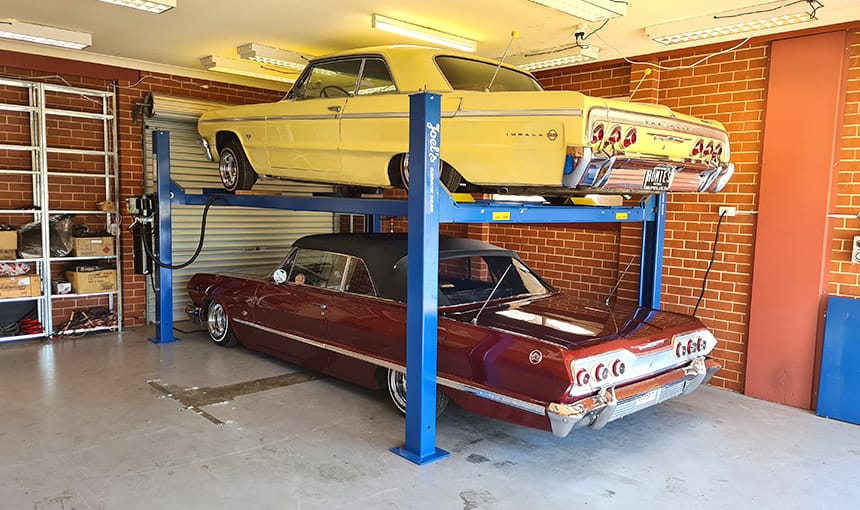
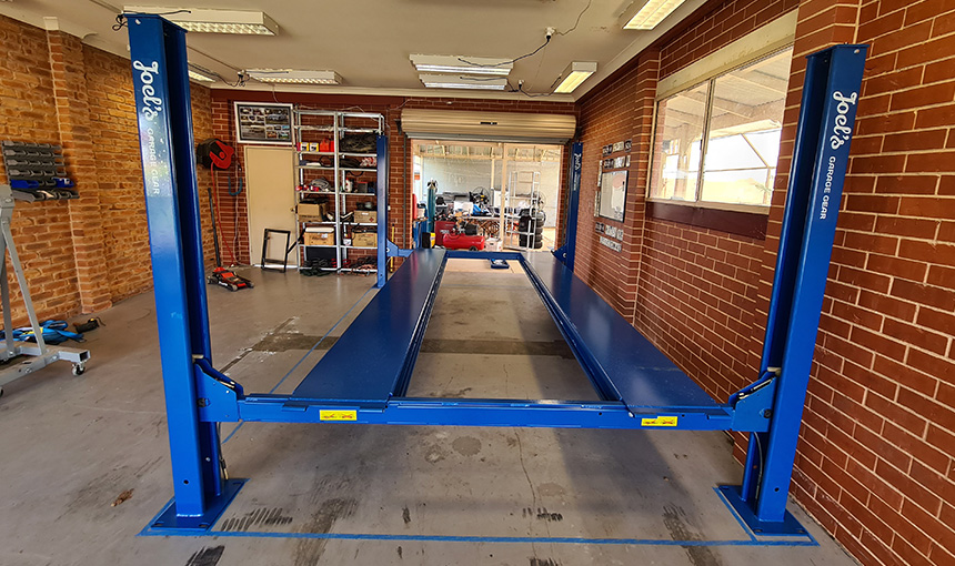
How-To Guide: Setting up a 4 Post Car Hoist
Need more storage space for your ever growing car collection? This guide will cover the steps involved in setting up a 4 Post Hoist DIY style with the help of your mates.
Prior to your purchase you would have measured the depth of your concrete and the height of your ceiling to make sure your space is suitable.
For this 4 Ton Standard 4 Post Hoist, we have 150mm of concrete and a 3 meter ceiling height in our garage.
Step 1: Collecting your new 4 Post Car Hoist
Ding! You’ve just been notified that your new 4 Post Hoist is ready for collection at your nearest freight depot and you need to go pick it up.
Most people will use a car trailer to do so, borrow or hire one if you don’t own one yourself and head to the collection address.
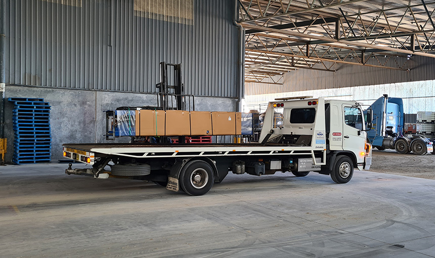
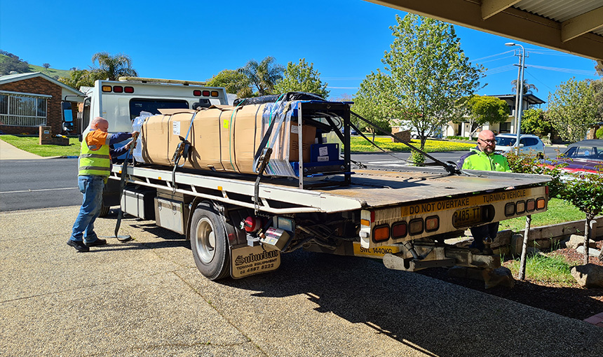
We decided to hire a tow truck with a tilt tray to deliver the hoist to our home address, as unloading 700+ kilograms without the help of a forklift isn’t as fun as it sounds.
Step 2: Unboxing your 4 Post Hoist
Begin by cutting and removing the packing straps and black plastic and carefully unload the four columns, both cross beams, the power unit and the remaining contents between the two runways.
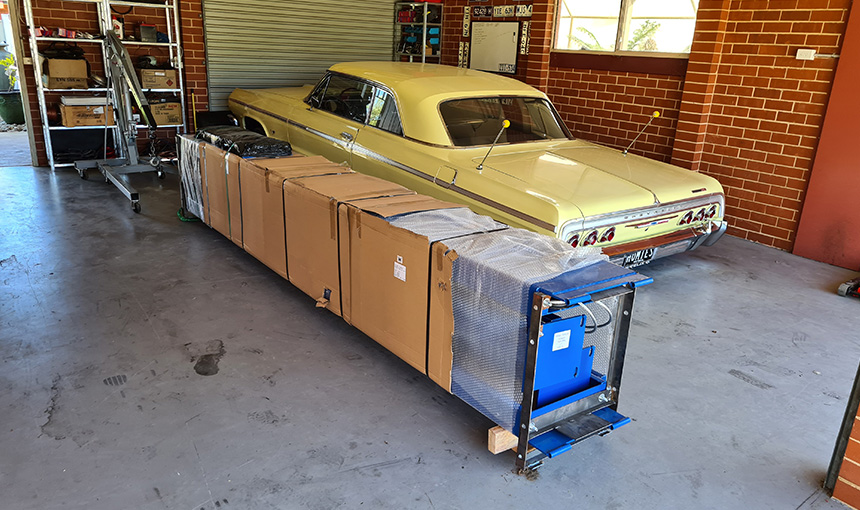
You can leave the runways where they are attached to the steel transport frames until it is time to install them.
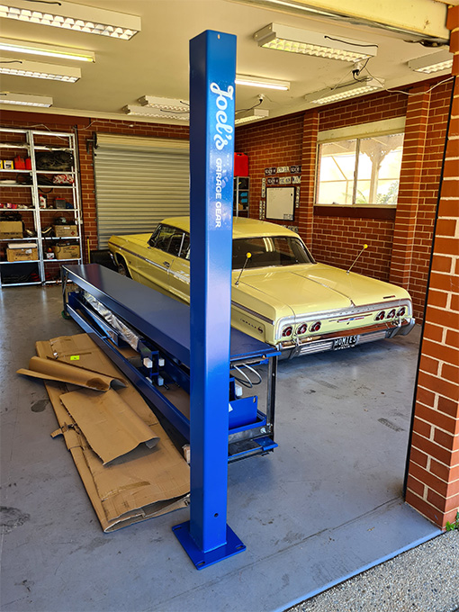
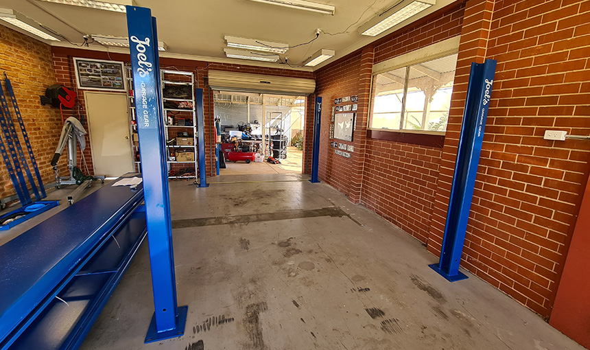
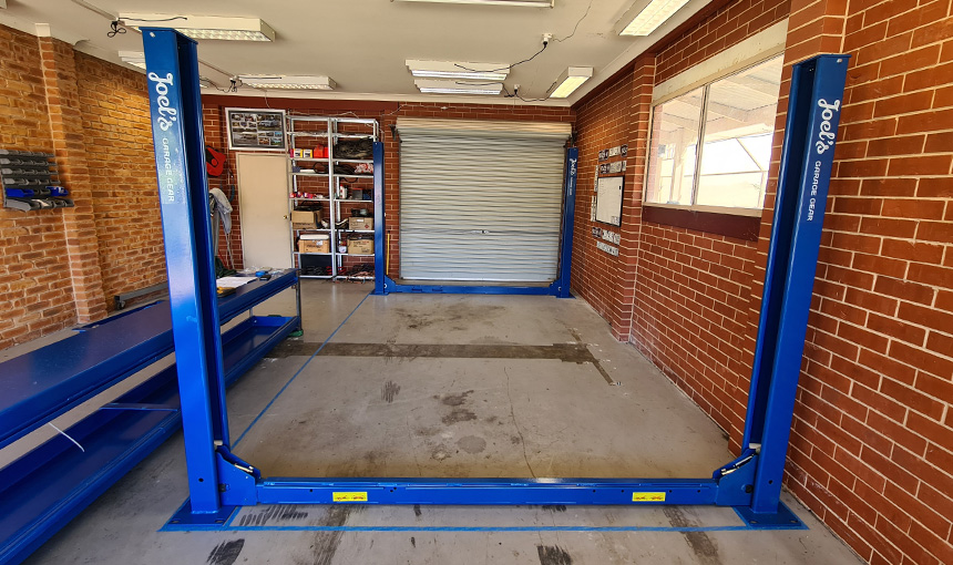
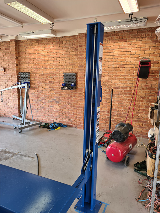
Step 3: Positioning of the four columns
Start by deciding which side you would like your power unit to reside on and move the column with the pump bracket into place on that side first.
The other three columns are all the same, so go ahead and measure the spacing between them according to the manual and move the remaining columns into place.
Although the measurements are more of a guide at this stage, it is still worth taking the time to align the columns as accurately as possible.
In order to check that the columns are square you can also measure diagonally across from the front left column to the rear right column and compare that with the diagonal measurement from the other two.
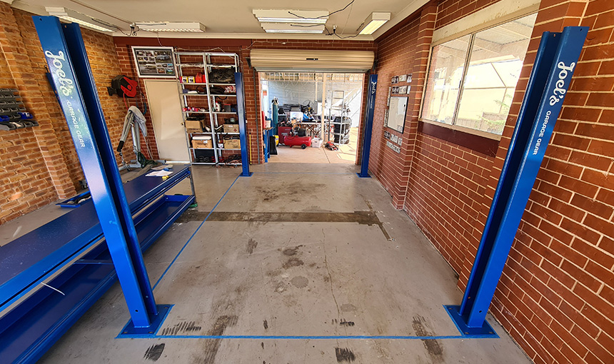
Step 4: Marking the layout of the columns
Once you are happy with the positioning of the columns, go ahead and lay masking tape on the floor around them, this will allow you to stand them back up in their correct spots after installing the cross beams.
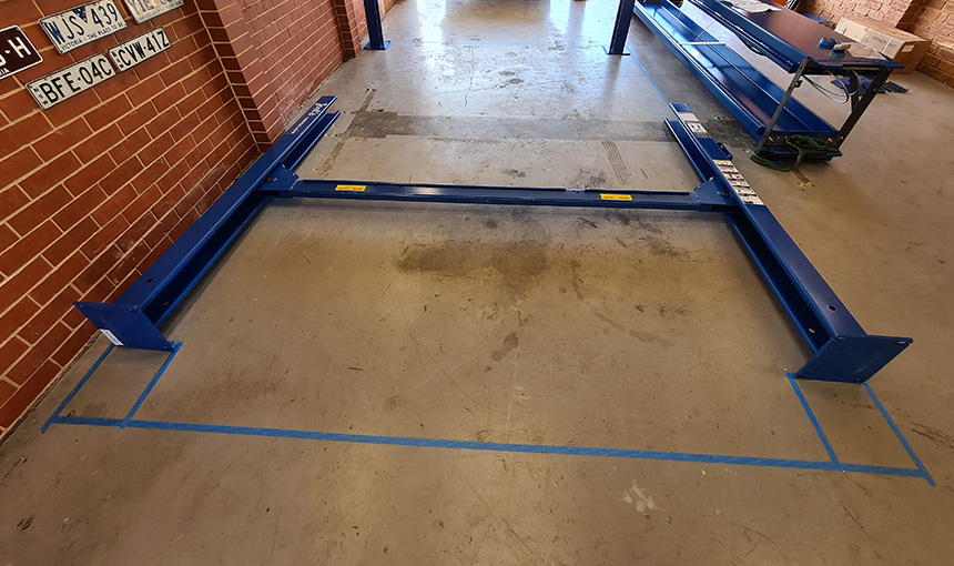
Step 5: Installing the cross beams
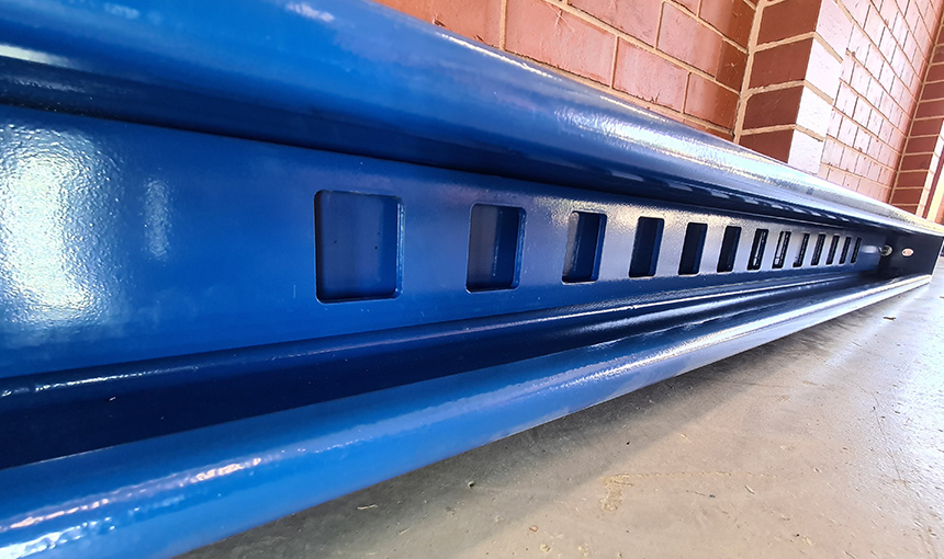
Firstly, note that the cross beams are not the same and need to be installed on the correct ends in specific directions.
The cross beam with small windows needs to be on the same end as the column that holds the power unit and the cross beam with large windows needs to be on the opposite end.
Both cross beams should have their windows facing each other as these are cut outs for the cables to run through.
Working on one end at a time, carefully lay the two columns down side by side. Check to ensure that the nylon blocks are correctly seated in place on the cross beam and that it is orientated in the correct direction.
Now insert the cross beam through the top of each column and slide it all the way down to the bottom. Repeat the same for the other end.
Step 6: Installing the ladders
All four ladders are identical, simply insert them in through the top of each column and slide them down until they reach the cross beam.
Then slide them through the guide slots in the nylon blocks of the cross beam until you feel them touch the bottom of the column.
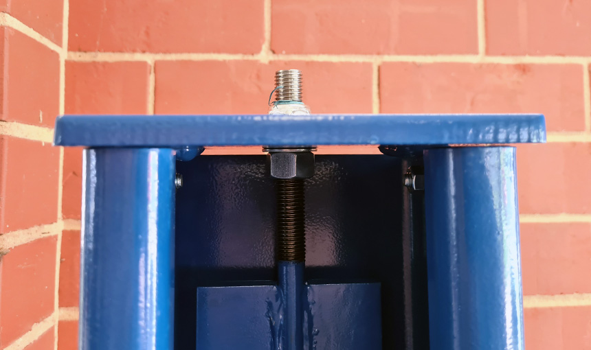
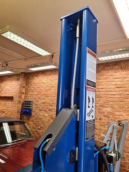
Step 7: Installing the top caps and standing up the columns
Ensure that the threaded rod on the top of the ladder has a nut and then a flat washer on before installing the top cap above it. Then place the top cap on and secure it with the two M8 bolts and nuts.
They should only fit on one way, but ensure that the other hole for the cable end to pass through is in front of the ladder. Then put another nut on the threaded rod above the top cap, followed by a nyloc nut.
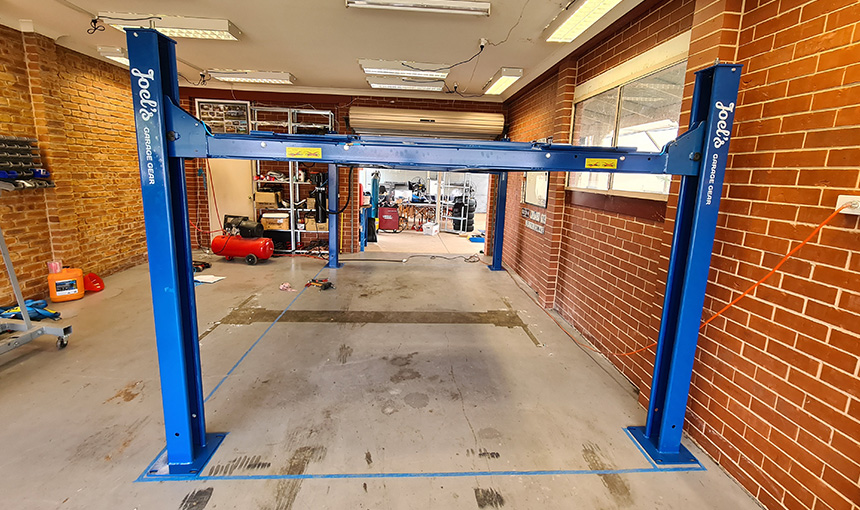
Now, with the help of a mate you can both lift a column each and place them back into the correct position according to the tape you laid down previously. Do this for both ends.
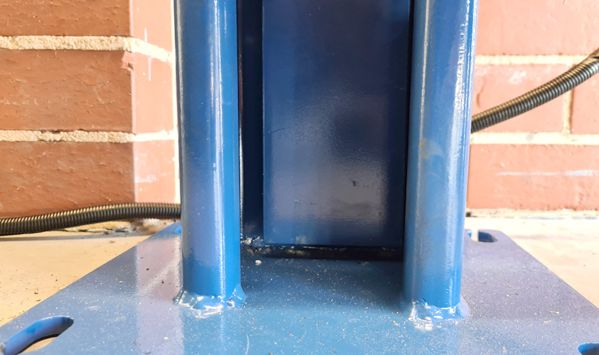
Step 8: Setting the ladder gaps
There must be a 1/2″ gap between the bottom of the ladder and the base of the column in order to prevent damage to the lift occurring.
In order to see the bottom of the column, you will need to raise the cross beam up. With the help of a mate you can raise it by hand and place a trolley jack underneath to support the weight.
You only need to raise it enough to see the bottom of the column, do not raise it to the height of the locks as yet.
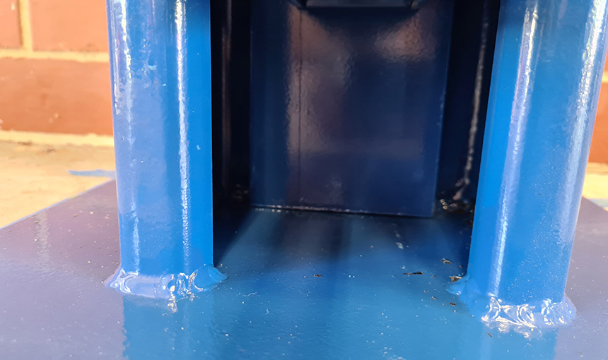
Now you can slacken off the bottom nut away from the top cap and then tighten up the top nut until the ladder raises up 1/2″ from the base of the column.
Once the gap has been set, tighten the bottom nut back up against the top cap to stop the ladder from pulling itself out when the lift is raised.
Each ladder should now be suspended from the top caps and not be sitting on the base of the columns. Ensure that the ladder gaps are set the same on all four columns.
Step 9: Setting the primary and slack safety locks
With the help of your trolley jack, raise the cross beams until they engage the safety locks into the first holes on the ladders. You can then release the jack as it will now support itself.
At this point, both the primary safety locks as well as the slack safety locks will be engaged in the ladder.
We don’t want this! The slack safety lock must not be engaged in the ladder as it is sprung loaded and should only ever activate in the event of cable failure.
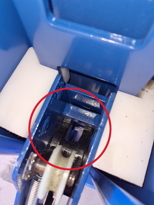
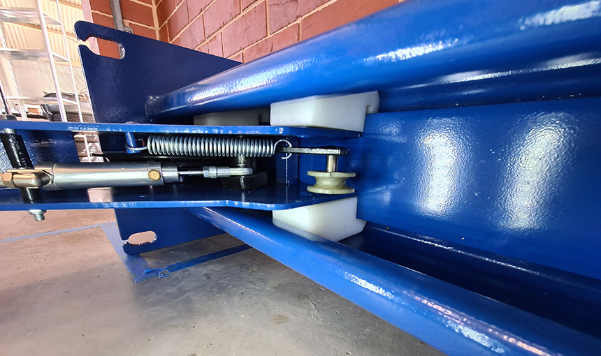
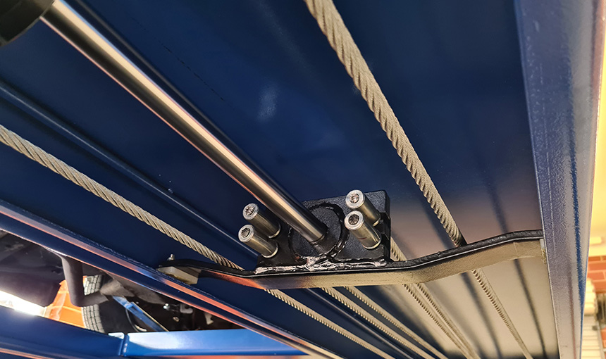
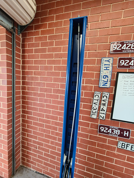
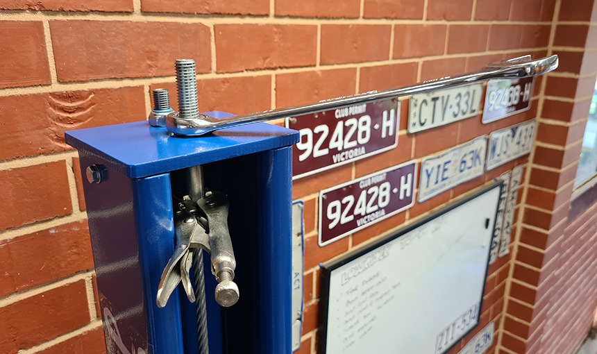
In order to set the slack safety lock correctly as pictured below, we need to raise the cross beam up a little more until the point where the safety locks are between the first and second holes in the ladder.
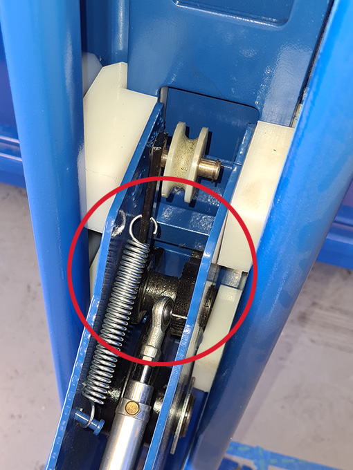
Once both locks are retracted back and no longer locked in to the ladder, with the help of a mate you will be able to press and hold each of the small cable pulleys in toward the columns in order to keep them retracted, whilst simultaneously lowering the jack.
This will allow only the primary safety lock to engage and the slack safety lock will remain retracted as shown. Once the cables are installed they will provide the tension required to keep the slack safety lock retracted.
Ensure the locks are correctly set on all four columns.
Step 10: Mounting the runways on the cross beams
There are two runways, one has a hydraulic cylinder as well as the safety cables on the underside of it and is referred to as the power-side runway. The other is referred to as the offside runway.
The power-side runway must be mounted on the side with the power unit column, with the utility rail facing inwards.
In order to move the runways safely the use of an engine crane is recommended. This is where the majority of the weight is.
Begin by taking the weight of the power-side runway with the engine crane and then undo the steel transport frames from both ends.
You will need a person at both ends to support the runway and a third person to maneuver the engine crane.
Once the runways are roughly in position you need to first run the four cables from the power-side runway through the windows in each cross beam and out to the columns.
You can then begin to properly locate each runway and bolt them down on to the cross beams one at a time, ensuring that the cables are resting below the bolts in order to prevent them from jamming.
Note that the offside runway has two sets of holes that it can mount to in order to change the track width depending on the vehicles you will be working on.
Step 11: Setting up the safety cables
You may have noticed that the safety cables aren’t long enough to reach beyond the ends of the cross beams. The reason for this is because the hydraulic cylinders stroke is not currently in sync with where the cross beams are sitting on the ladders.
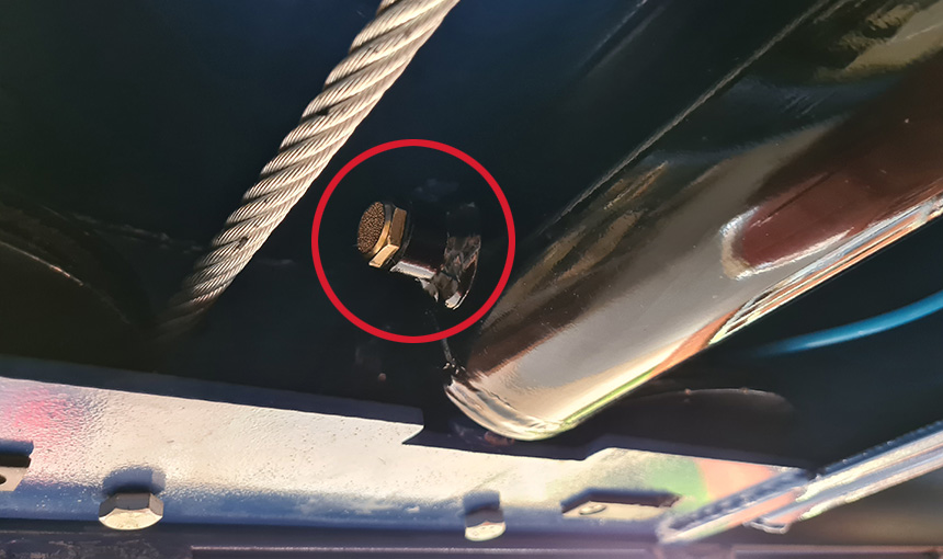
In order to get more cable length we need to extend the cylinder manually. To do this we need to first remove the brass plug at the bottom of the cylinder.
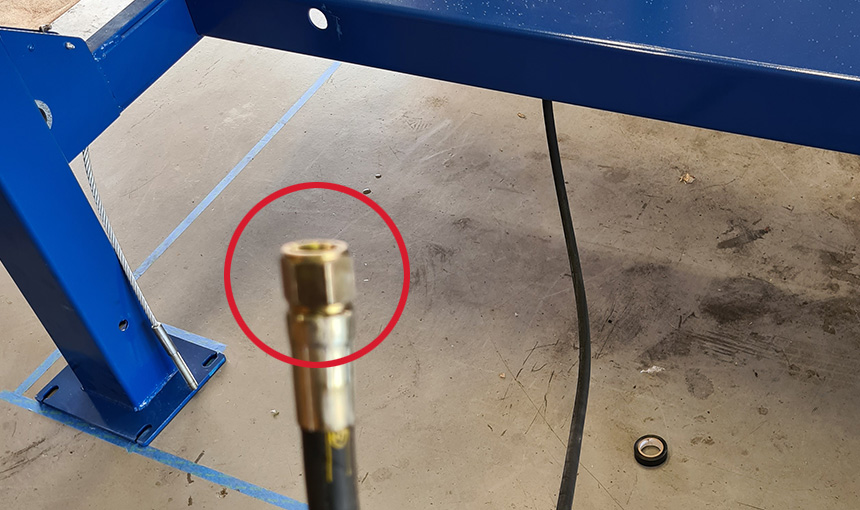
You also need to remove the red plastic bung from the end of the hydraulic hose that goes to the power unit.
With these undone, air can escape and we won’t be fighting the vacuum. You can now lay under the power-side runway and pull the end of the cylinder out by sliding the nylon blocks along the underside of the runway.
This will give you more cable slack at each corner and allow you to pull the cables up through the slack safety pulleys and out through top caps on each column.
You can then add a nut on to the exposed thread in order to remove some of the excess safety cable slack, followed by a nyloc nut to lock it in place.
Don’t forget to put the brass plug back into the hydraulic cylinder with some teflon and tighten it!
You will need to ensure that there is around 1″ of thread sticking up past the nut on the top cap for each column in order to eliminate any excess safety cable slack.
Care will still need to be taken when first operating the hoist to ensure that the cables remain in their pulleys. This will be resolved once we tackle the final cable adjustment.
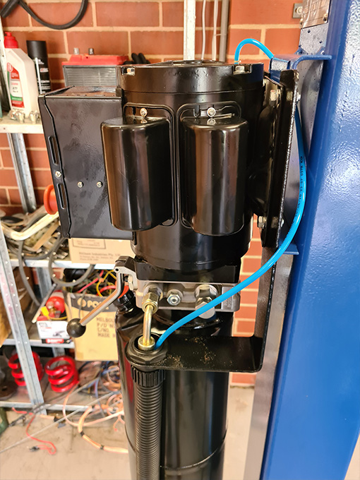
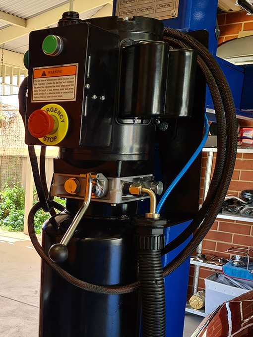
Step 12: Mounting the power unit
Attach the power unit to the mounting plate using the nuts and bolts provided. There are two extra brackets that need to be attached as well, one for the hose protector and the other for the pneumatic switch.
Once you have mounted the power unit you can connect the hydraulic hose from the cylinder.
First run it through the tabs under the power-side runway and then out through the hole in the side. Attach the plastic protector before you connect the hydraulic hose to the power unit using the extra 90° fitting provided.
Please note: The hydraulic hose pictured below is different to the one that comes included with your hoist.
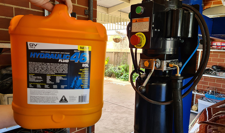
Step 13: Filling the tank with hydraulic oil
Now that you have attached the hydraulic hose and double checked all of your fittings are tight, it is time to fill the tank with ISO 46 hydraulic oil.
Remove the dipstick and fill the tank with roughly 11 litres of hydraulic oil or till it becomes visible towards the top of the dipstick.
Note that you may need to top it up once you have run the hoist up and down a few times to bleed the air from the system.
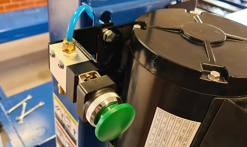
Step 14: Connecting an air source to the safety lock release actuators
Begin by attaching the pneumatic switch to the bracket provided. We chose to replace the bottom push fitting with a 1/4″ BSP Nitto style fitting in order to attach our air compressor directly to the hoist.
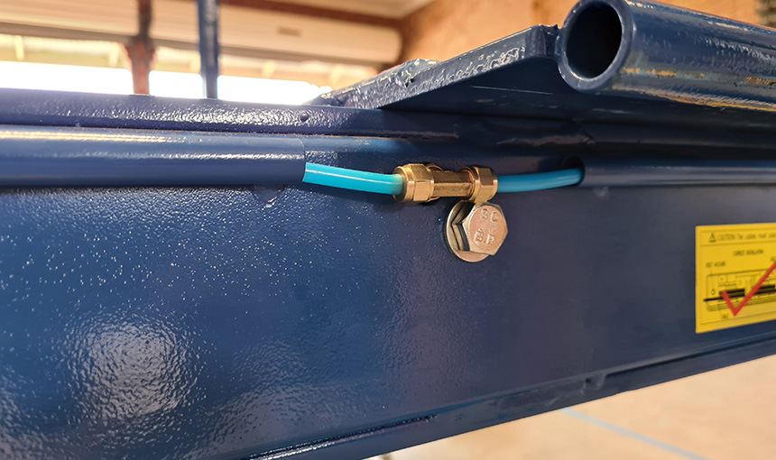
From there we ran air line around the power unit bracket and in alongside the hydraulic hose in order for it to enter the power-side runway.
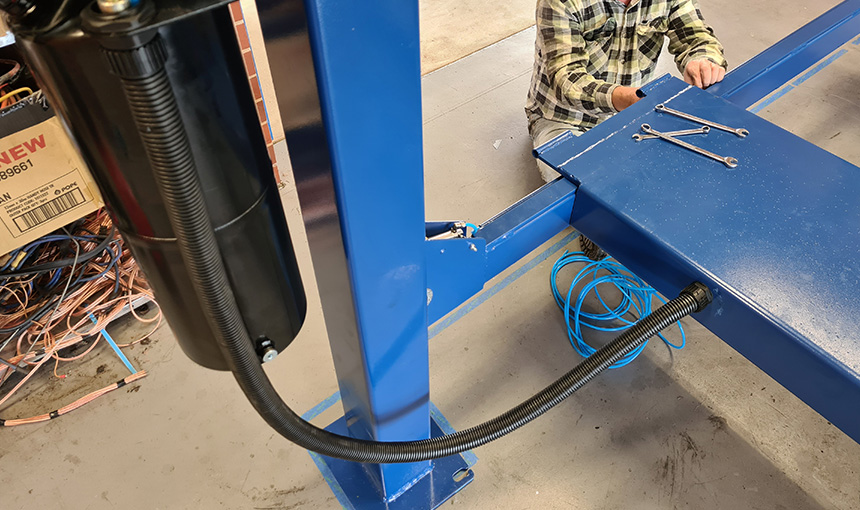
Once under the power-side runway it continues through the air line channel provided in order for it to not rub on any of the cables.
It then enters a tee fitting that splits the air line between each end of the hoist.
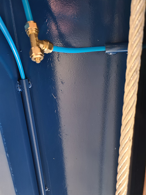
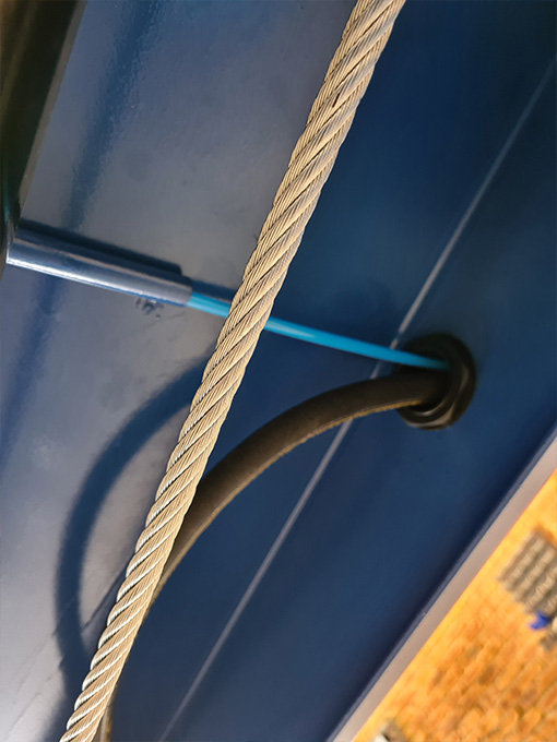
It then comes out of the extra hole in the cross beam on both ends of the hoist and goes directly into another tee fitting that splits it between the left and right columns.
These channels lead the air hose to its final destination, which is the safety lock release actuators situated at each individual column.
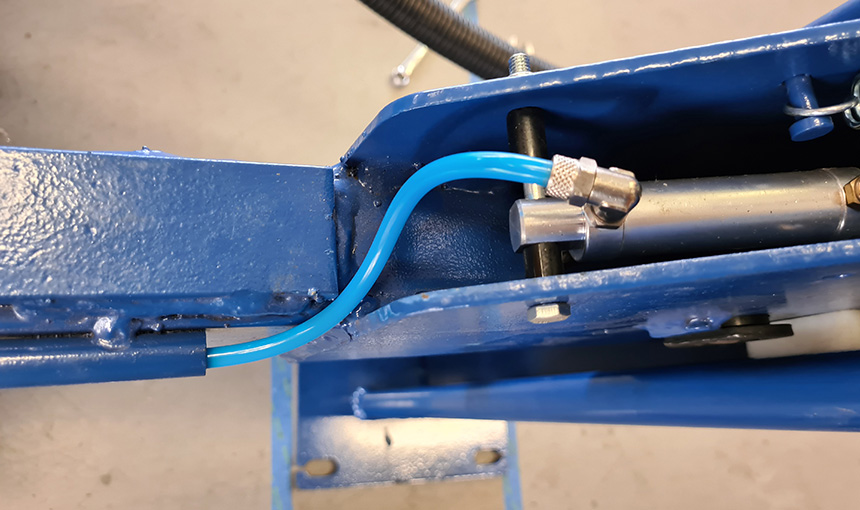
Once you’re done you can press all four caps on to the cross beams in order to protect the safety lock release actuators.
Step 15: Wiring up the power unit
With the air hose connections tightened and checked, the pneumatic locks are now able to be released. However, in order to do so we first need to raise the hoist slightly and for that it will need power.
Please note that you will need a certified electrician to wire up the 16AMP power unit for you. It is illegal to carry out this step yourself and we do not recommend that you do so.
Step 16: Leveling the runways and adjusting the safety cables
With the hoist secured on the first safety locks, we can now begin leveling the runways.
If you are sure that your concrete floor is level you can simply use a tape measure to ensure that the four ends of the runways are at the same height.
If they aren’t, simply adjust the ladder heights until they match, making sure that the ladders don’t end up resting on the bottom of the columns.
If your floor isn’t level you will need to use a laser level across the runways or a very long spirit level instead.
Once you have your runways sitting level with the hoist on the locks, raise it a few centimeters further until the safety cables take the weight.
Now measure all four corners again and then adjust the cables this time in order to level out the runways. This should now have all four locks clicking in sync as you raise the hoist up.
Step 17: Bleeding the air from the hydraulic system
Head over to the power unit to begin the bleeding process. Start by making sure that the emergency stop is out and power up your hoist until you reach maximum travel.
Then release the safety locks by pressing the pneumatic switch and use the lever to let the runways all the way back down.
This can be a slow process with no weight on the runways. You may also notice that the hoist operation will be jerky to begin with, this is due to air escaping from the lines.
You will need to repeat the process of cycling the hoist up and down two or three times until a smooth operation is achieved, which means the air has been bled correctly.
You should also hear the safety locks click at the same time going up if you have adjusted your cables correctly. If they are still slightly out of sync you will need to make some final adjustments to the cables by ear until they align with each other.
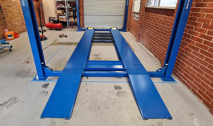
Step 18: Installing the ramps & wheel stops
Position the ramps in place on the end that you would like to use as the entry point. Then simply slide the pins through the guides on the cross beams and through the ramps in order to attach them.
You can then insert the provided split pins to keep them secured in place. Repeat the same for the wheel stops on the other end, with the flat edge facing the top.
If you purchased any extras for your 4 Post Hoist such as the Optional Jacking Plate or Plastic Drip Trays now is a good time to install them as well.
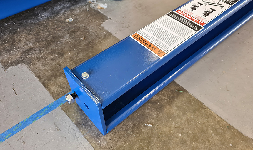
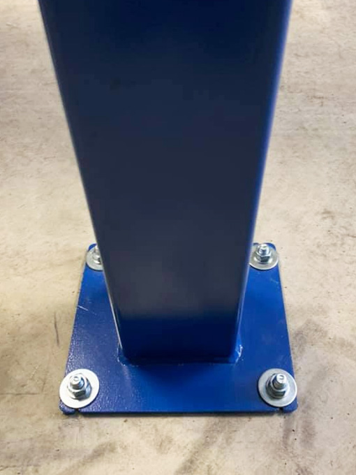
Step 19: Anchoring your hoist to the concrete
Now that your 4 Post Hoist is completely assembled and unlikely to move it is time to secure the columns to the concrete.
Begin by drilling the four 16mm holes to the correct depth on each column and then use compressed air to clear out the concrete dust before driving in your anchors with a large hammer.
Once completed, tighten all of your anchor bolts down until they are firmly secured.
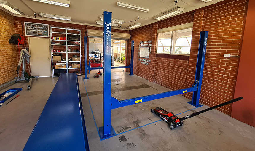
Step 20: Lifting and lowering your vehicle
So your new hoist is finally all set up and ready to be used for the first time. All that’s left to do now is to carefully drive your car on to it.
Once you’re happy that the car is securely parked and it is safe to lift, you may raise it to your desired height. You will hear the safety locks clicking as the hoist rises.
When you reach your desired height, make sure that you use the lever to lower it down onto the primary safety locks before working under it!
When it comes to going back down, the hoist will have the primary safety locks engaged and you will not be able to lower it without first raising it slightly.
In order to lower your vehicle, first press the button to raise the hoist off the safety locks a few centimeters. Then press and hold the pneumatic switch whilst at the same time pulling the lever down.
That concludes our guide on how to set up your new 4 post hoist. Whilst it may seem daunting at first, it is a relatively straight forward process for most hands on car enthusiasts.
With the help of a few mates, it shouldn’t be more than a days work. It will however save you hundreds of hours when working on your car!

Ready to purchase this hoist for your home garage?